The subject of grounding in electronics is broad and complex, spanning a variety of functions and objectives. In this article, we will investigate the applications and regulation of grounding in control systems on a fundamental level

Grounding is usually grouped into two main areas: personal safety and signal conditioning. The rules surrounding usage are dictated somewhat by which category the situation requires.
The first category is grounding for equipment and personal safety. This category includes all residential and industrial machinery connections and follows very specific regulations on wire sizes, locations, colours, and resistances.
The second category is grounding for the purpose of signal conditioning. Grounding can help reduce problems in low-voltage and high-speed digital communications. This makes it a very important discussion when dealing with industrial networks, digital circuits, and radio frequency (RF) applications, among many others.
Functional Earthing (FE) Sometimes called Instrumental Earth
Functional earthing is basically equipotential bonding; this is the discharge of coupled transient currents that build up on screens or an FE function in device parts for people with non-dangerous voltages. The same applies to couplings on the ground leads inside equipment. These, too, must be safely discharged.
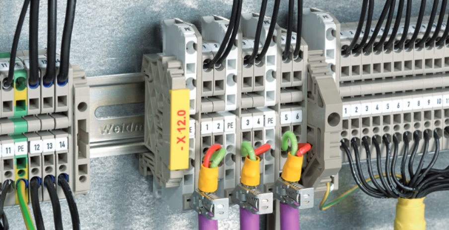
These clips are made of metal because metals are good conductors of electricity and can easily transfer the EMF voltages away from the cable. The clips are designed to fit over the cable braid and make a secure connection to the metal shielding. Once connected, these clips help to dissipate the electromagnetic fields generated by the cable and prevent any interference or noise that may affect the performance of the electronic device connected to the cable. The use of metal clips is a common practice in electronics and is an effective way to shield cables from unwanted EMF.
Protective Earthing (PE)
The main purpose of PE is to protect people against indirect contact. In a TT or TN system, if a phase has a fault against a metal conductive part, PE is the conductor that takes the fault current away and, by doing so, tells something (maybe an RCD) that the power supply must be disconnected.
First, it's important to ensure that all metal parts that can be touched by people are connected to the PE conductor. This includes metal enclosures, pipes, and other conductive elements that are not part of the electrical circuit but could become live in the event of a fault. It is also essential to verify the continuity of the PE path, as any interruption could lead to a dangerous situation.
Secondly, the choice of the PE conductor's size should follow the same criteria as the other conductors, taking into account the maximum fault current that may occur and the distance between different PE connections. It's important to remember that the PE conductor doesn't carry current under normal conditions, but it must be able to carry it safely in the event of a fault.
In summary, the PE conductor is a vital part of the electrical system, providing a safe path for fault currents and protecting people against indirect contact. Proper installation, sizing, and continuity of the PE conductor are crucial for ensuring a safe and reliable electrical installation.
Intrinsic Safety Earth (ISE)
Intrinsic Safety Earthing (ISE) is a type of protection technique that limits the energy that can be transferred to hazardous areas. ISE is typically used for sensing electronics, and it relies on energy control to prevent ignition. Unlike PE, ISE may or may not involve a connection to Earth, but it always requires careful consideration of the amount of energy that can be stored or transferred.
A good example of ISE is the screen of the connecting cable. As we saw before this is addressed as an FE, but, as we know, the Intrinsic Safety protection method relies on energy control for its safety. The screen, if not well treated, may store too much energy and this is a safety issue. So, while we were very relaxed in regard to FE, we now have to be very strict in following rules because we always have to know how much energy is stored in our ISE. The original purpose is solely functional, but as it exists, ISE has to be really taken care of.
Lightning Protection System (LPS)
A lightning protection system (LPS) is a series of measures designed to protect a building or structure from the damaging effects of lightning strikes. The system consists of three main components: the lightning rod, the conductor system, and the grounding system.
The lightning rod, also known as a lightning conductor or air terminal, is a pointed metal rod located on the roof of a building. Its purpose is to intercept lightning strikes and conduct the electrical current safely into the ground. The conductor system, made up of metal cables or strips, carries the electrical charge from the lightning rod down to the grounding system.
The grounding system, which is typically composed of metal rods or plates buried in the ground, dissipates the electrical charge safely into the earth. When lightning strikes the lightning rod, the electrical charge is transferred to the conductor system and then to the grounding system. This prevents the lightning from causing damage to the building's electrical systems, appliances, and other structures.
In addition to protecting buildings and structures, lightning protection systems can also protect people and animals from the harmful effects of lightning strikes. However, it is important to note that no lightning protection system can provide 100% protection from lightning strikes, and caution and common sense should always be exercised during thunderstorms.
Comments